Welcome to the VVT Beast Version 2.0 update page. As if version 1.0 wasn’t rowdy enough. The posts here are from newest to oldest, so the most recent post will show up when the page is opened. Some links are affiliate links. Enjoy the build! (Last Update: 2/28/2023) Engine assembly video is here. First drive video is here. Full build list is here. DYNO DAY VIDEO IS HERE!

This will be the final post on the engine build blog, it’s been real! Further updates on the car will likely go to other pages, as well as on my Instagram and YouTube Channels. Check out the dyno day for this beautiful engine here.


Well folks, the moment, or at least one of the moments I’ve been awaiting for the last year: The first drive in VVT Beast V2.0. I broke in the rings, changed the oil, checked out the oil filter internals (which looked clean), and drove her to work. Everything is going good so far, but it’s always nerve-wracking!

Until this happens. The AN fittings I’ve used for my turbo’s water feed for the last 5 years finally started leaking, and leaking a lot. Some AN fittings (like the one pictured) have an internal o-ring on the hose end. This is what allows the hose to rotate after assembly, but it’s also a failure point. I’ve ordered these Push Lock Fittings which don’t have o-rings, and don’t even require clamps. Push the hose on and go. I’m using 3/8″ EFI hose with these which will both lock onto the barbs properly and hold up to cooling system pressures. (Don’t use vacuum or PCV line).


Getting a nice early start on this day. With some coolant, some Lucas Break In Oil, a string alignment, and a final bolt-check; it should be time for the long awaited start up.


The beast has a heart again! Dropping the engine and transmission in as one unit was a piece of cake. Now onto hooking up all of the electronics, fuel system, cooking system, intake piping, and the rest of the driveline. It’s almost time to fire this thing up!

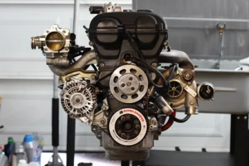
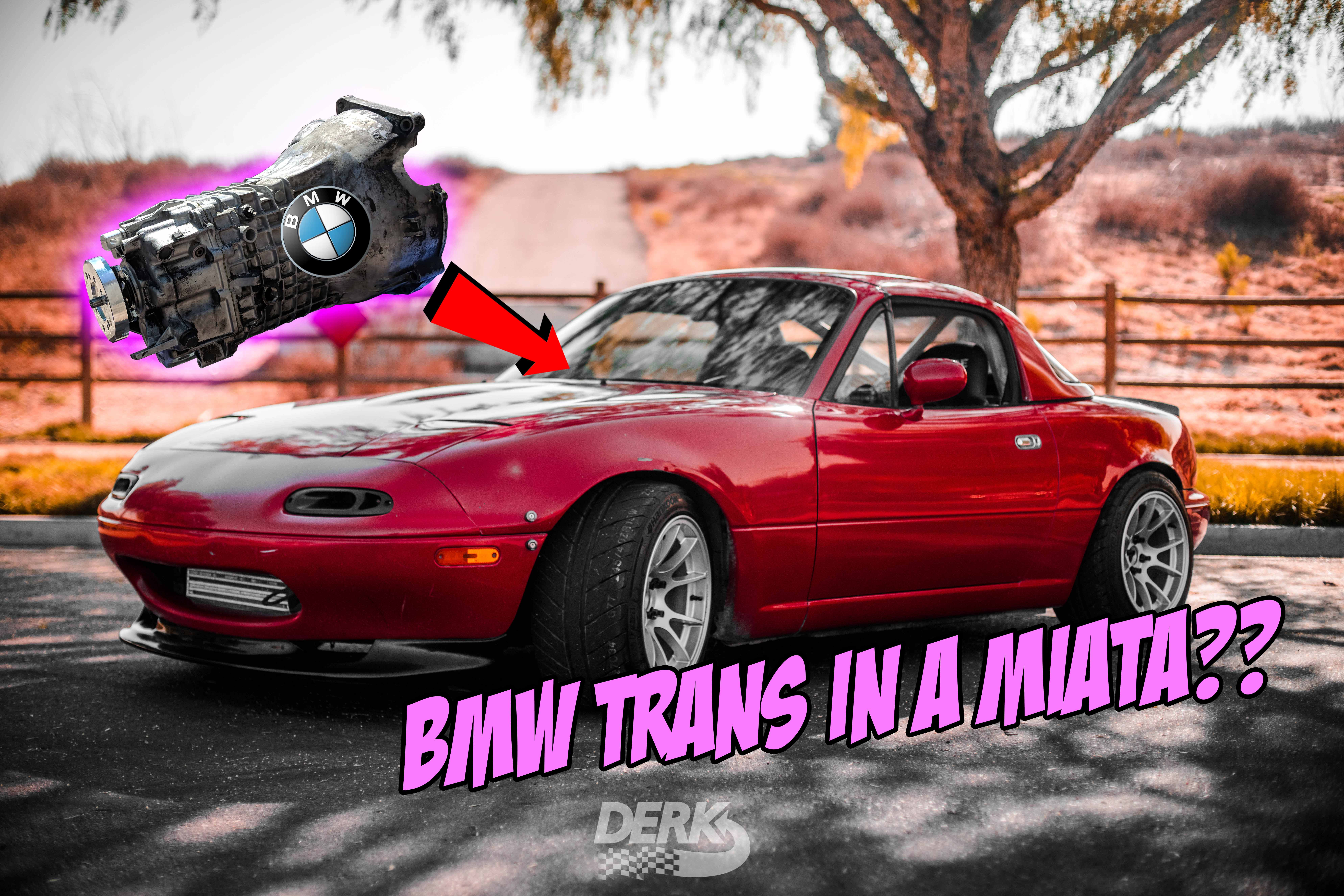
Here’s the complete package. All mated up to a BMW ZF 5-Speed from a Z3, one of the strongest bolt-in conversions for the Miata. The engine is essentially ready to drop in at this point.


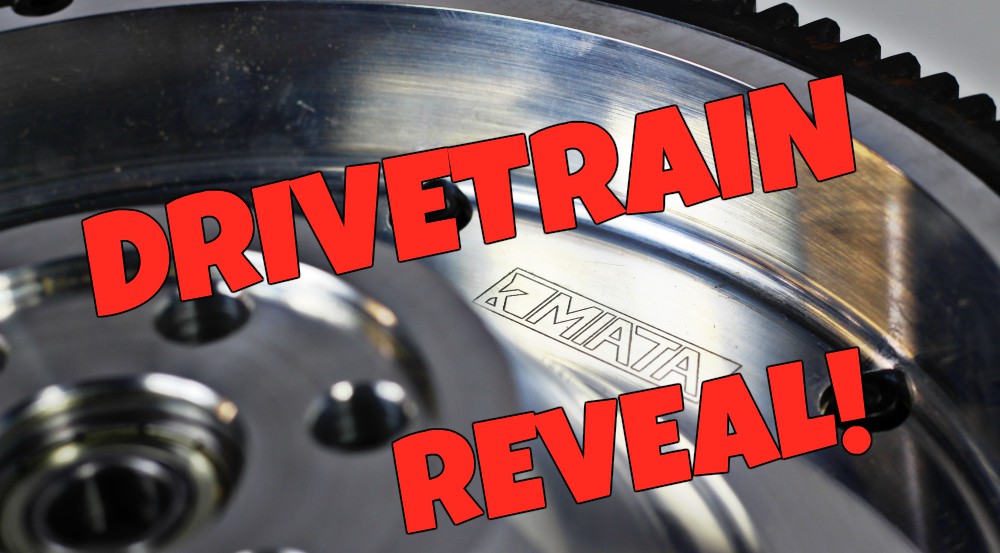
The clutch & flywheel setup is as follows: a KPower Industries 13lb flywheel (Which is part of the E36/E46 ZF Transmission Conversion Kit), ACT Xtreme pressure plate (For E46), and ACT Sprung 6-Puck disc. Read more about choosing a clutch here: Left Foot Magic: Choosing a Clutch. The previous setup was identical except for the HD pressure plate which, although rated for 500lb-ft, experience very occasional slip under heavy abuse. The Xtreme is rated for around 700lb-ft of torque, more than this engine will ever make.

And the heart of this powerhouse: a Borg Warner EFR6758 with an internally gated 0.64 A/R turbine housing. I always tell people who ask me questions about using higher compression, stroker cranks, bigger bore pistons, and E85/tuning to increase engine response and turbo spool-up time: The turbo itself, along with a free flowing exhaust and proper boost control, will give you 90% of your powerband characteristics. All the other stuff is just chasing a few percent here and there. You’ll also notice the diverter valve, which replaces a traditional blow off valve but recirculating excess boost within the compressor housing, has been upgraded to a Turbosmart Kompact unit that replaces the weak OE plastic housing with aluminum. It’s also been upgraded with a Turbosmart GenV IWG-75 dual-port wastegate actuator for easy spring swapping and a super wide range of boost pressures.


The rest of the hardware on this engine is all the same as V1: Skunk2 intake manifold, Skunk2 throttle body, Kraken bottom-mount exhaust manifold, NA8 alternator (internally regulated), and ATI Super Damper.


Head: installed. Valve cover and front covers: Installed. Advanced Engine Dynamix Coil-On-Plug Kit: ready to ignite some highly pressurized ethanol. Which will be injected through a Radium Engineering fuel rail and Injector Dynamix 1300cc injectors. The head build is exactly what I ran on the previous engine, no changes. BP6D head (2001 – 2005), stock cams, upgraded valve springs of unknown origin (but tested at 91lbs seat pressure), SI Valves exhaust valves, and Manley intake valves (both stock sized). The head has been shaved about 0.040″ (1.0mm).


With the valvetrain all clear, it’s time for the final head install. I went with a set of Fab9 Tuning 2800 Ultra Duty head studs. Partly because the ARP’s were out of stock everywhere for months, but these head studs are supposedly even beefier than the ARP’s.

Another little technical note: You need to use a head gasket while doing the clay test, and it needs to be the thickness of the one you’ll be using ont he running engine. Since I’m using a grooved fire-ring style head gasket, I can’t install the head for clay testing purposes with that gasket. In order to simulate the 1.3mm head gasket thickness, I took 2 of my old Cometic MLS 1.0mm gaskets, drilled out the rivets, and stacked the thin layers until achieving the perfect thickness (at only 35lb-ft of torque) for testing this extremely tight clearance. The individual layers of an MLS are razor sharp. I’ve officially added blood to the sweat and tears of this build.

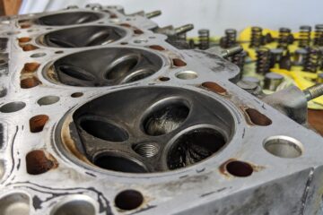
Pictured here: the clay test, post modding. We are in BUSINESS. Side note – the clay test was done with the intake cam advanced by 3 teeth, which is 46.97° of intake cam advance. This is as close to simulating full VVT advance as you can get (which is actually only 44°, hooray for extra safety margin). I only ran a max of 30° on the prior engine, but you NEED to clearance the motor for full advance. If this was a non-VVT motor, this wouldn’t even be CLOSE to being an issue especially with stock cams.


I’ve marked out with sharpie the approximate amount I’m going to try to bring the walls of the valve reliefs back, it ended up being closer to 2mm in the center of the reliefs. After that it’s just a matter of shaving down the pockets, and doing the clay test again. Obviously, it’s very important to not let any of the shavings get into the engine. Another popular question is, “aren’t you worried about the engine balance after modifying the pistons by hand?” And the answer is, not one bit. I’ve probably removed about a gram of aluminum from each piston, which is negligible, so I’m certainly not worried about the difference in weight removed between the 4 pistons. We’re talking about fractions of a gram. Just imagine the weight of all of the oil that rides on the pistons/rods while the engine is running.

You can see from the “clay test” (Put clay in the valve reliefs, install the head and timing belt, turn engine over slowly, remove head and cut the clay in half to see how much valve clearance you have) that the valve is contacting the flat part of the piston above the valve relief. The short explanation for this is due to the ~1mm head shave and 2mm stroker crank, the valves no longer open into the reliefs at the “stock” angle/position. Watch this short video for a more in depth explanation.

I kind of expected this. Here, I’m prepping to take a dremel to a set of $600 pistons. Why? Clearance issues, keep reading to find out.

Whenever your pistons actually go above the block at TDC (Top Dead Center), you need to be especially concerned with squish clearance. This is the distance between the cylinder head and the piston at TDC. Stock is around 0.051″ (1.30mm) but down to 0.030″ (0.76mm) should be safe enough, allowing for heat expansion. The squish area is where the air/fuel mixture is forced up into the combustion chamber where the fun happens, and there does need to be a small gap there. You can see the pistons are pushed above the block deck slightly by the stroker crank, but when I install the head gasket fire ring, it’s clear to see how much squish clearance there will be. The pistons protrude 0.020″ (0.50mm) above the block, the fire rings are 0.051″ (1.30mm) thick, which means the squish on this engine is 0.031″ (0.79mm). Beautiful.


Let’s talk about the piston setup and the compression ratio of this engine. There are several things other than piston selection that affect the compression ratio of an engine. I encourage you to open up a compression ratio calculator to follow along, it’s fun to see how the different parts change it! Now if you just slap a set of those into an otherwise stock BP, the calculated compression actually comes out closer to 10.0:1. So what else changes compression you ask? Bumping up from 83mm to 84mm pistons takes compression from 9.83 to 10.03. The ~1mm head shave, which reduced the combustion chamber from 52cc to 46cc, raises compression from 10.03 to 11.21. Since I’m running a thicker head gasket (1.3×84.5mm vs. the stock 0.8×83.5mm) compression drops to 10.60. But here’s where it gets juicy. Increasing the stroke from 85 to 87mm raises compression again from 10.60 to 10.83, but a side effect of using the stroker crank with stock length rods, is that since the pistons are 1mm higher at TDC, they’re pushed slightly into the head gasket area (pistons sit +0.5mm over the deck, rather than -0.5mm under the deck) which takes compression from 10.83 to 12.08. Now since I did have to remove a little material from the pistons for valve clearancing, that does reduce compression slightly. I’m estimating that each piston lost approximately 1cc of aluminum, and that leaves compression at 11.83:1. The larger bore and stroke also raises engine capacity from 1839cc (stock) to 1929cc. The previous engine (“V1”) was right at 9:1/1884cc. The quest for the most responsive 400hp+ turbo BP continues, I can’t wait to see how it performs.

Now it’s starting to look like an engine! The oil pan is sealed up, and the water pump and oil pump are bolted into place. The oil pump is a Boundary Engineering Stage II (Which is the high volume version, recommended for VVT engines, and when using lots of oiled accessories like turbos and oil coolers). I went with 2 shims this time, which targets 72psi of oil pressure.


Hello again, Captain Overkill here! Just kidding, I only say that because my Miata is just a street car, that lives 99% of its life on the street. But it does get a little rowdy in the canyons sometimes, and with the big sticky Nankang AR-1’s this car will see some g-forces. It’s a good thing this DCBE.Tech sump baffle with viton trapdoors will help keep oil where it needs to be – at the oil pump pickup.


The 2001-2005 Miata engine uses what’s called a Main Bearing Support Plate (MBSP). But it’s got an interesting design choice: it only supports Main #1, #2, #4, & #5, but not #3. Now maybe #3 doesn’t need the support as much as the others, the engineers may be able to tell you that. But the engineers also built this engine for just over 100hp, and in my book, there’d be no harm in a little extra support, right? So what you see here is the comparison between the stock MBSP, and the 5-Main version offered by MiataRoadster. This MBSP supports all 5 Mains, comes with ARP hardware, and comes pre-clearanced for ARP Main studs. (If you use the stock MBSP with ARP Main studs, you have to drill and cut it to fit). And best of all: IT’S SHINY!


Let’s talk about these pesky oil squirters. The Wiseco pistons interfere with the stock squirters, and the typical solution is to delete them and put delete bolts into the holes. I’m not here to debate over which is better, most people say the benefits of deleting the squirters are: lower oil temperature, less oil consumption, and higher oil pressure to the bearings. I decided to keep the oil squirters which I believe have the benefits of: keeping the pistons cooler and helping lubricate the cylinder walls. Do your research, and make the decision for yourself! If you are using Wiseco pistons, be aware that you will need to put a bit of an “S” bend on the squirters, it’s a bit of a trial-and-error process. The stroker crank also sends the pistons 1mm lower at BDC (Bottom Dead Center) which brings them closer to the squirters. As you can see from the pictures, it’s a very tight fit. They need to clear the pistons and ALSO the bigger rods as they change angle and location through the engines cycle.


Lots of shiny parts here that are about to get covered by an oil pan, but it’s what’s inside that counts right? The core of the engine is complete now, sporting a set of Manley H-Beam rods and Wiseco 84.0mm, 10.5:1 compression pistons. The pistons also have upgraded 0.185″ wrist pins from Trend Performance. I tried to get the 0.175″ variants but they were out of stock, I’m pretty sure the 0.185″ pins can hold like, 1000hp. It’s overkill, but there are rumors floating around that since the 10.5’s are considered “N/A” pistons, they use a thinner wrist pin that may not hold up to loads of forced induction torque. Better safe than sorry. And about the compression – the pistons are called “10.5” but since this engine has undergone so many other changes, that will not be the final compression ratio. I’ll get into that in a later post.


Next up is filing the rings. I went with a 0.017” (0.43mm) top ring and 0.019” (0.48mm) 2nd ring. I did this because that’s what I ran on the previous engine and I didn’t have any issues, although I’m hearing from some knowledgeable sources that even up to 0.022” (0.56mm) is fine, and safer, for a high power application. When the rings heat up, they expand. If the ends of the ring contact each other, they have no more room to expand and can seize the engine or rip off the top of the piston. Bad news! Refer to the instructions included with your rings. The comparison shot shows the visual difference between a gap that you’d see on a stock Miata engine, compared to what’s needed for a higher power application. Barely any difference, but it matters! The tool I used to file the rings can be bought here, and I found that using medium pressure, 35-40 cranks removes about 0.001” of material. Test fit often to make sure you don’t remove too much!


Starting with the bare block, I bolted in a set of Mazworx billet main caps from Bofi along with some ARP Main Studs to check the bearing size. I already had the block align bored (100% necessary when replacing main caps). I know I just said this engine won’t be breaking any power records, but I want it to be stronger than before, and have headroom… just in case I do decide to upsize the turbo later on.

V2 is going to have the same goals in mind. In fact I’ll be up front and say it will have less peak power than V1. Why? Because the EFR6758 was being overworked at 500hp+. At 30-32psi it was spinning around 172,000RPM while Borg Warner recommends capping it at 154,000RPM. I enjoy finding the limits of things, but I know the tune on the Beast was a little too hot. The turbo should be plenty happy at 430-450whp which is still incredibly fast in this 2300lb NA6. But if I’m going through all of the work of building a new engine, you bet your rear main seal I’m making improvements. So I tried to pick things that would build on what I already loved about the power, and wouldn’t cost me any torque in the lower RPM range. I got a Maruha Motors 87mm Stroker Crankshaft from Bofi Racing (Stock is 85mm) which takes displacement from 1884cc to 1928cc. Longer stroke and more displacement equals more torque, and faster turbo spool up. On top of that I’m raising the compression ratio from 9.0:1 to 12:0:1, which should help make even more torque with the same amount of fuel and air.

But the best part about V1 wasn’t its peak power. See my NA is a street car, and I want it to behave as such. I use it for cruising in the city, touge runs, drag racing, autocross; pretty much every kind of driving, not just roll races and highway pulls. So I always aimed for a super responsive build, and maximizing torque under the curve. Originally this engine was able to produce 300wtq by 3700RPM which as far as I know is one of the best performing BP’s in its category.

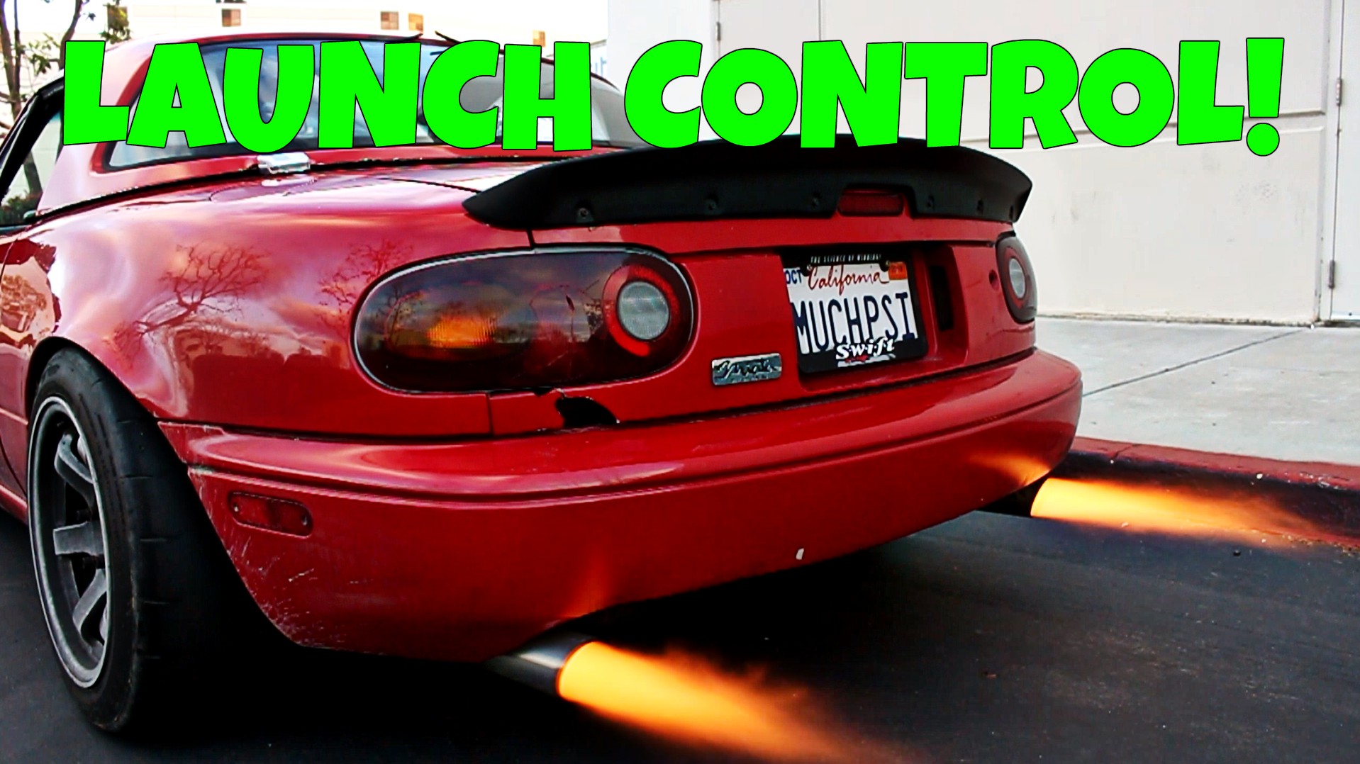
V1 met its fate on the highway as well, with a very aggressive tune and a personal record breaking 5.85s 100-200km/h time (that’s pretty darn fast. Like Lamborghini Aventador LP700 fast. Like $300,000 Turbo Porsche fast.) Here’s a video of that run. It was fast, but unfortunately I discovered the strength limit of the cast iron main caps. Yeah, that’s 3 out of 5 caps that hold the crankshaft in the engine.

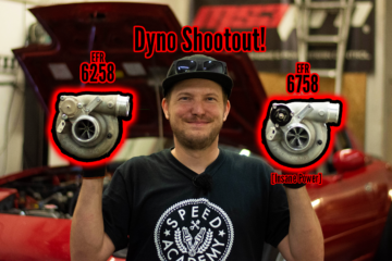
As a bit of a recap, in case you’re new here, this is VVT Beast Version 1.0. A fire breathing, ethanol drinking, 1884cc BP6D that peaked at 523whp/465wtq on a Borg Warner EFR6758 (Although it lived the majority of its 15,000 mile life with an EFR6258 producing just over 400whp you can see that engine’s full setup here). It served as a replacement for the car’s original 1.6L engine which ejected a connecting rod on Interstate 15 on the way home from making 295whp on the dyno.

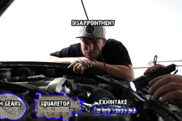
The look you make when your Miata just made over 500HP.